9v Dc Power Supply Circuit Diagram

But some current drop r4 through r6 in parallel.
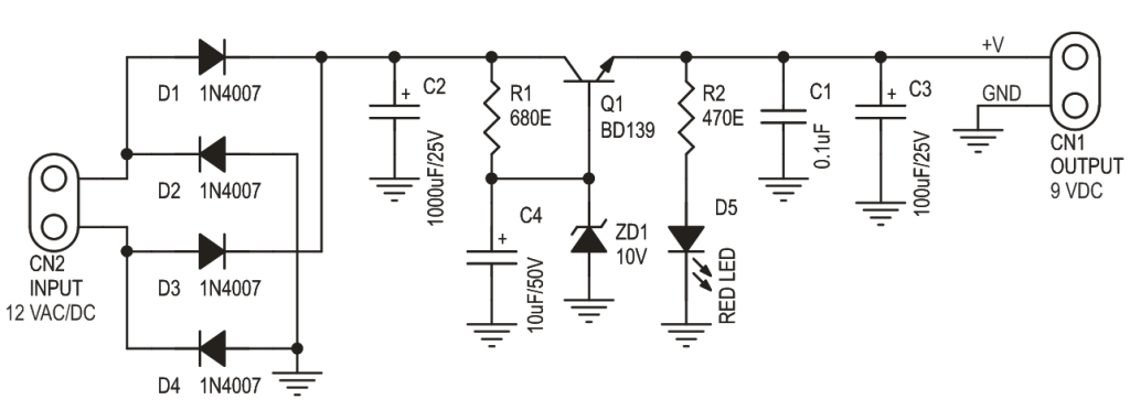
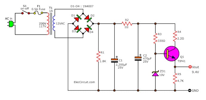
9v dc power supply circuit diagram. The output voltage is the same as the voltage drop across the zener diode zd1. The 7809 is a 9 volt voltage regulator ic with features such as internal current limit safe area protection thermal protection etc. Here is the circuit diagram of 9 v regulator using popular 7809 ic. A single power supply can provide as many as voltages as are required by using a voltage or potential divider as illustrated in the figure.
We can adapt the old components to make the 9v regulated power supply circuit that can give current 500ma to 2a. From the principle above. We try to set this circuit. 79xx ic used to regulate the negative input voltage where as the 78xx ic used for positive input dc voltage regulate.
Variable dc power supply october 12 2010 a variable dc power supply is one of the most useful tools on the electronics hobbyist s workbench. Many 9v regulated power supply circuit using transistor and zener diode or non some one so easy and cheap than ic 7805. Dc power supply schematic diagram. The output is not regulated of this circuit.
This is the general 12 v dc dual power supply circuit. Here we have designed dual polarity 5v power supply from 9v battery. The circuit uses a 16v output tranformer from 230v mains. The following circuit diagram gives regulated dual power output regulator ic is used in these circuit.
Often more than one dc voltage is required for the operation of electronic circuits. A 16 v transformer brings down the 230v mains 1a bridge rectifier rectifies it and capacitor c1 filters it and 7809 regulates it to produce a steady9v dc output. This is a circuit of a 9v power supply using lm7809 ic. This is 9v dc power supply no transformer it is an easy circuit and small size.
Learn how to use zener diode. As illustrated in the figure a potential divider is a single tapped resistor. When the circuit is connected to. Lm7809 is a famous ic with many features like output current 1 5a fixed output voltage 5 volt to 24 volt thermal shutdown current limiting etc.
We ll now go over each part of this circuit and go over the role each component plays so that you can know how this circuit works. The output is lower 35ma. There is little to be said about this circuit. Circuit diagram with parts list.
Regulated power supply diagram. Below is the schematic for the dc power supply so that we can see how all the parts are connected and are brought together. It s a simple project of a dc dc converter to make a phantom power supply for professional microphones. Here is the circuit diagram and explanation for transformerless power supply.
We can convert the high voltage ac into low voltage such as 5v 6v 9v 12v dc without using the transformer which is called transformerless power supply. It should be 70ma. Above are the parts needed to create a dc power supply. The current can be found 7ma current for 0 1uf capacitor.


